
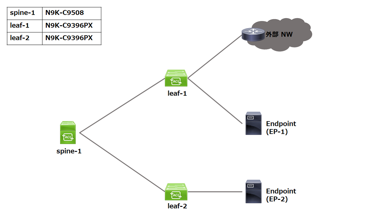
TASK
EP-2 からEP-1 および外部NW 宛にPing とSSH 通信が可能となるようにしてください。
なお、Route Reflector の設定は完了しているものとします。
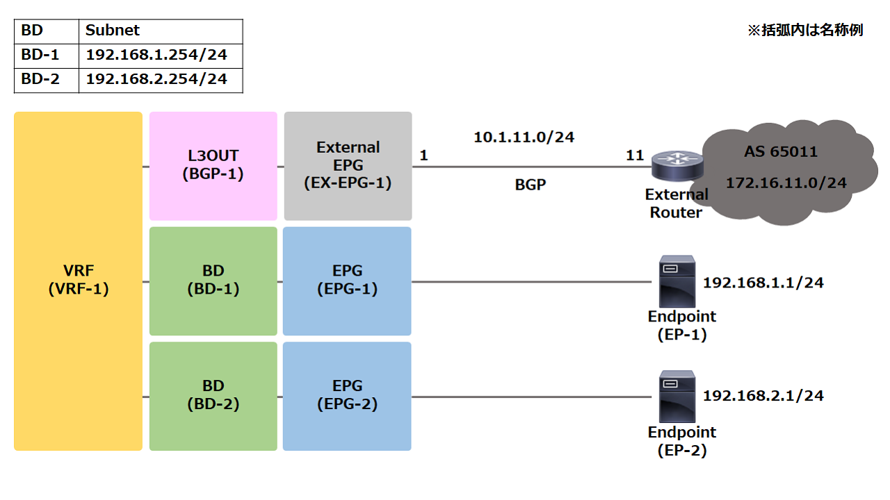
DIAGRAM
CONFIGURATION
BGP Route Reflector 設定
System > System Settings > BGP Route Reflector > default
- Autonomous System Number (任意)
- Route Reflector Nodes (Spineを指定)

Fabric > Fabric Policies > Pods > Policy Groups
を右クリックし、Create Pod Policy Group
- Name
- BGP Route Reflector Policy (1で設定のdefault を選択)

Fabric > Fabric Policies > Pods > Profiles > Pod Profile default > default
- Pod Selectors > Policy Group に2で作成のPolicy Group を指定
- Type とBlocks はALL のままでOK

SpineからCLI で show bgp vpnv4 unicast summary vrf all でLeafとネイバーが張れていることを確認
Access Policy 設定
Access Policy は全て Fabric > Access Policies 配下で設定します。
Pools > VLAN
を右クリックし、Create VLAN Pool
- Name (任意)
- Allocation Mode (Static を指定)
- Encap Blocks
  – Range (任意のVLAN ID を指定)
  - Allocation Mode (Inherit かStatic を指定)
  - Role (デフォルト)

Physical and External Domains > Physical Domains
を右クリックし、Create Physical Domain
- Name (任意)
- VLAN Pool (作成済みのVLAN Pool を指定)

Physical and External Domains > External Routed Domains
を右クリックし、Create Layer 3 Domain
- Name (任意)
- VLAN Pool (作成済みのVLAN Pool を指定)

Policies > Global > Attachable Access Entity Profiles
を右クリックし、Create Attachable Access Entity Profile
- Name (任意)
- Domains (作成済みDomain 2つを指定)

Policies > Interface
から任意の項目を右クリックして作成する
例 Link Level Policy
Create Link Level Policy
- Name (任意)
- Speed (1 Gbps を指定)

Interfaces > Leaf Interfaces > Policy Groups > Leaf Access Port
を右クリックし、 Create Leaf Access Port Policy Group
- Name (任意)
- 前項で作成した任意のInterface Policy を指定
- Attached Entity Profile (作成済みのAEP を指定)

Interfaces > Leaf Interfaces > Profiles
を右クリックし、Create Leaf Interface Profile
- Name (任意)
- Interface Selectors
  - Name (任意)
  - Interface IDs (他との重複NG)
  - Interface Policy Group (作成済みのInterface Policy Group を指定)

Switches > Leaf Switches > Profiles
を右クリックし、Create Leaf Profile
- Name (任意)
- Leaf Selectors
  - Name (任意)
  - Blocks (Leaf ID を指定)

Next をクリック後にInterface Selector Profiles から作成済みのInterface Profile をチェック
Tenant 設定
Tenants > Add Tenant
- Name (任意)
これ以降は全て作成済みのTenant 配下で作成します。
Networking > VRFs
を右クリックし、Create VRF
- Name (任意)
- Create A Bridge Domain はチェックを外す

Networking > Bridge Domains
を右クリックし、Create Bridge Domain
- Name (任意)
- VRF (作成済みVRF を指定)

Next

- Subnets
  - Gateway IP (192.168.1.254/24)

※ 同様に2つ目のBridge Domain も作成
Application Profiles
を右クリックし、Create Application Profile
- Name (任意)

Application Profiles > Application Profile 名 > Application EPGs
を右クリックし、Create Application EPG
- Name (任意)
- Bridge Domain (作成済みのBD を指定)

※ 同様に2つ目のEPG も作成

Application Profiles > Application Profile 名 > Application EPGs > Application EPG 名
を選択し、Navigation ペインを開く
Domains (VMs and Bare-Metals)を右クリックし、Add Physical Domain Association
- Physical Domain Profile (作成済みのPhysical Domain を指定)

Static Ports を右クリックし、Deploy Static EPG on PC, VPC, or Interface
- Path Type (Port)
- Node (Leaf を選択)
- Path (インタフェースを選択)
- Port Encap (VLAN ID を指定)
- Mode を選択

※ Node, Path, Port Encap はAccess Policy で設定した範囲から指定
※ 同様に2つ目のEPG もDomain とStatic Port を設定
Contracts > Filters
を右クリックし、Create Filter
- Name (任意)
- Entries
  - Name (任意)
  - EtherType (IP)
  - IP Protocol (icmp)

- Name (任意)
- Entries
  - Name (任意)
  - EtherType (IP)
  - IP Protocol (tcp)
  - Destination Port / Range (22/22)

※ Port のUnspecified は any
※ プルダウンに無いプロトコルは手入力でPort番号を指定
※ 単体Port を指定する場合はfrom/to に同じ番号を入力

Contracts > Standard
を右クリックし、Create Contract
- Name (任意)
- Scope (VRF)
- Subjects
  - Name (任意)
  - Filters (作成済みのFilter を追加)

Application Profiles > Application Profile 名 > Application EPGs > Application EPG 名 > Contracts
を右クリックし、Add Provided Contract / Add Consumed Contract のいずれかを指定

※ 同様に残りのEPG にもProvided Contract / Consumed Contract のいずれかを指定
ここまで設定してEP 間の通信が可能になる
L3OUT 設定
Networking > External Routed Networks
を右クリックし、Create Routed Outside
- Name (任意)
- VRF (作成済みのVRF を指定)
- External Routed Domain (作成済みのLayer 3 Domain を指定)
- BGP にチェック

- Nodes and Interfaces Protocol Profiles の+印をクリック
  - Name (任意)
  - Nodes
    - Node ID (Leaf を選択)
    - Router ID (任意を指定)
    - Use Router ID as Loopback Address はチェックを外す

  - Interface Profiles
    - Name (任意)
      Next (2.Protocol Profiles はそのままNext)
    - Interface Typeに応じて+印をクリック(Routed/SVI/Routed Sub-Interface)
    - Path Type (Port)
    - Node (Leaf を選択)
    - Path (インタフェースを選択)
    - IPv4 Primary Address (任意)
    - BGP Peer Connectivity Profiles の+印をクリック
      - Peer Address
      - Remote Autonomous System Number
      - 他任意
(Next まで戻る)
Next
External EPG Networks
- Name (任意)
- Subnet (0.0.0.0/0 か任意)
- scope (External Subnets for the External EPG)
ここまで設定してBGP Peer 確立、プレフィックスの受信が可能になる
(ACI 内のプレフィックス広報はまだできない)
BD Subnetを外部に広報するためにScopeを変更する
Networking > Bridge Domains > Bridge Domains 名 > Subnets > Subnet を選択
Private to VRF ⇒ Advertised Externallyに変更

※ 同様に残りのSubnet もScopeを変更する
ルートマップ用のプレフィックスリストを定義する
Networking > External Routed Networks > Match Rules for Route Maps
を右クリックし、Create Match Rule for a Route Map
- Name (任意)
- Match Prefix (BDのSubnetを指定)
ルートマップを定義する
Networking > External Routed Networks > L3 OUT名 > Route map for import and export route control
を右クリックし、Create Route Map for import and export route control
- Name (プルダウンから default-export)
  ※Warning は閉じる
- Type (Match Routing Policy Only)
- Contexts
  - Order 0-9 を入力
  - Name (任意)
  - Match Rule (作成済みのプレフィックスリストを指定)
ここまで設定してBD Subnet がBGP で広報される
(EP と外部NW 間の通信はまだできない)
Contractを定義する
– External EPG とApplication EPG の間にContract を設定
– Contract 作成とApplication EPG への適用は省略
External EPG への適用
Networking > External Routed Networks > L3 OUT名 > Networks > External EPG 名
Work ペインからPolicy > Cntracts > タブを選択
Provided or Consumed Contracts に追加
今回の要件はEP-2 からの通信なので、External EPG はProvider (Provided Contracts) になる
以上